A few months ago, I made a setup with Lego to measure time and speed. I had 3 measurement points. One measurement then put another measurement further away and a third a few cm further away. This allowed me to measure the time to make 1m standing start and have the speed at 1m.
I also used it to measure the maximum speed of the car by going full throttle.
The setup was a bit archaic, not easy to adjust at each setup and only 3 sensors along the track. So I thought about improving the system!!!
I ordered a while ago what to do it but I didn’t have time, at the moment, I have a little more time and I dove into the components and the code.
First encouraging tests.
For this test, I chose the easy way, I quickly assembled the son’s First circuit.
I have a Raspberry Pi connected to a board to distribute the connections.
Connected to it, I have a relay, a 3-diode traffic light, a temperature, hydrometry, atmospheric pressure sensor and 2 boards of 4 infrared sensors.
So I have 8 vehicle detection points.
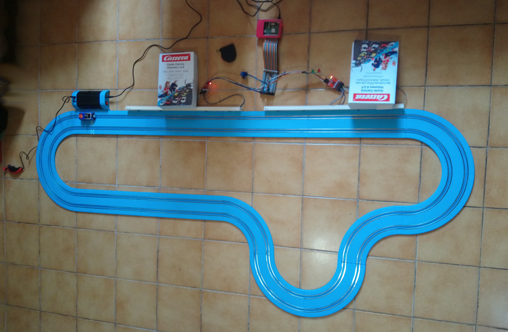
I have 4 points on each white strip (electric chutes) that we see at the top of the track held by the books.
distance of the measurements: 10cm, 20cm, 10cm and 20cm further on the second strip 10cm, 20cm, 10cm. Distance between the 1st sensor and the last: 1 meter
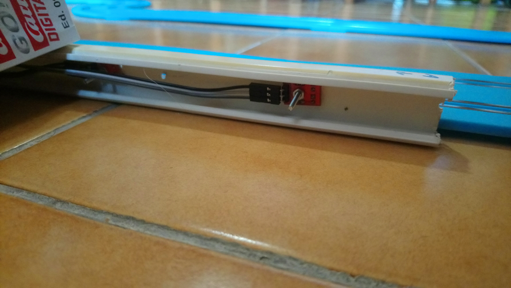
Zoom on the mini PC and the board:
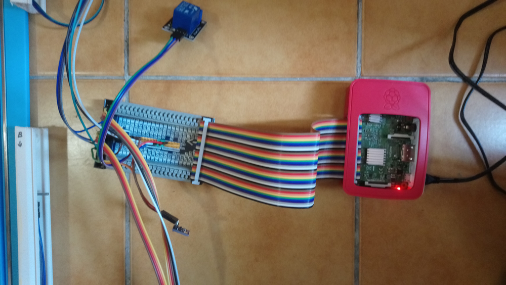
We see the relay (blue) at the top which will allow to connect a controller to take control of the car. And at the bottom the T°, Hygrometry and pressure (weather) sensor
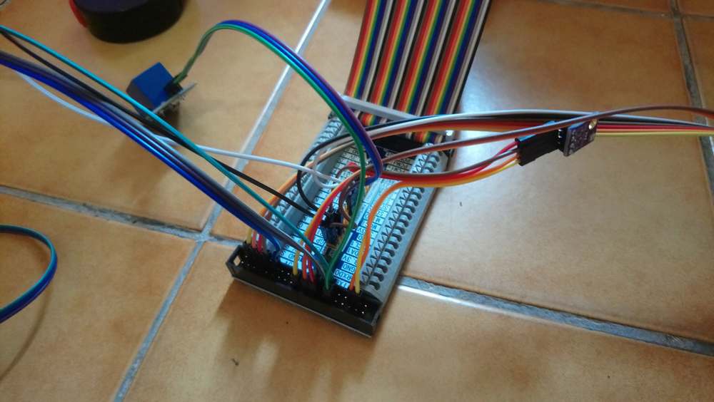
Another view :
The board that manages the 4 car presence sensors:
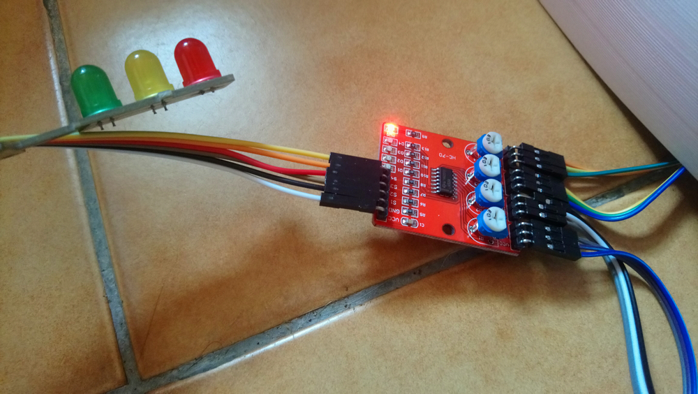
At the top we can see the traffic light
The transmitter and receiver diodes to the left of the screws:
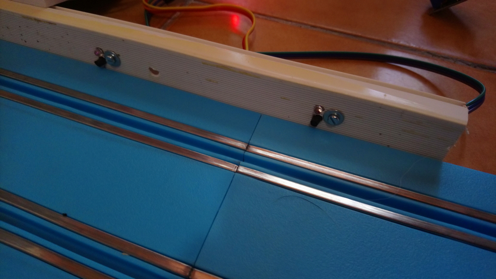
It is fixed on an electrical chute
Rear view:
Electronic equipment budget:
Excluding Raspberry: around €10
I tested the 4 First cars.
I retrieved the text file generated by the program, a quick look in Excel and voila:
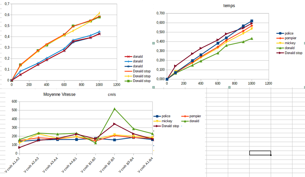
I tested the Donald car in 2 configurations, like the others, from a rolling start, full throttle and once from a standing start, flush with the 1st sensor. Each test has 3 attempts to get an average and eliminate any parasitic readings
The curve at the top left is Donald’s, it’s fairly regular as readings.
I must have a problem with the reading in zone B2-B3, because I have a shift on each curve in this zone. The sensor must not detect the car at the same level, which explains a difference on certain cars only.
Coming soon, the test on the GO circuit.